
What is a CNC Wood Lathe Machine?
WHAT IS A CNC WOOD LATHE MACHINE ?
CNC Wood Lathe machines are machines that can produce cylindrical and conical, helical (threaded) parts, as well as parts that are processed from a blank (makta) by attaching mirrors, such as plates, vases, etc. In addition, CNC wood lathe machines are 2, 3, 4 and more axis machines that can perform complex carving, such as cabriole (lükens) furniture legs and motifs on them, sculptures.

Schnitzer Wood Lathe machines are 2, 3 and 4 axes and it is possible to make all of the foot types listed above.
In CNC Wood Lathe machines, it is also possible to produce square or polygonal section parts and open drill or rivet holes in legs. In many varieties of Schnitzer CNC wood lathe machines, normal lathe cutters, together with caterpillars, triangular, square or cylindrical cutters, top blades, and pen blades are used. Also, some models of the machines with sanding addition can be seen.
Some models of Schnitzer CNC Wood Lathe machines have an automatic part feeding (charger) unit for mass production. Cutter tool magazines can be of linear or rotary types. Some machine models may have drilling and hole units. They are controlled by a control unit.
A user-friendly CAM program, which is developed for Schnitzer CNC wood lathe machines, allows for perfect turning operations with any two and three-dimensional drawings.
PARTS OF WOOD LATHE MACHINE
FRAME (BODY)
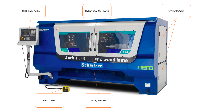
In Schnitzer CNC wood lathe machines, safety is at the forefront. The machine is designed as a closed cabin, and is designed to be connected to a dust collector system for rough dust and chips. A detail from the internal view of the machine is given in the relevant image.

SPINDLE- SPINDLE SHAFT- DEAD CENTER
The spindle and spindle shaft are classic lathe machine elements. The spindle is a closed, box-shaped element that can be opened when necessary, and contains the mill and belt-pulley system inside. The spindle shaft and the dead center attached to it are the elements that rotate the workpiece, via the motor and belt-pulley system. The dead center has a sharp tip, and has teeth that bite into the workpiece, so that the workpieces do not spin freely when they are pressured. In CNC machines, the belt-pulley system is replaced by direct connection to the motor, and the speeds are set according to the characteristics of the work, via the CAM program.

In CNC wood lathe machines, these mechanisms and the motor are designed to easily handle heavy and large parts, and the tips work on a pneumatic system.
In the pneumatic pressure system, the pressure can be adjusted according to the dimensions of the part.
The corners of thick parts to be processed do not have to be cut in advance, also prevents the part from flying off by holding center-drilled parts well.
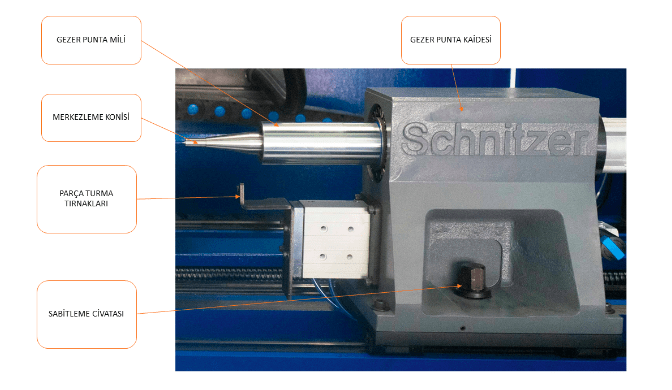
TRAVELING TOOL REST AND CONICAL SPINDLE
The traveling tool rest is an element that can be moved and fixed according to the length of the piece, opposite the spindle in longitudinal turning operations. It has a conical spindle attached to the tip (centering cone) or in some types of machines, it can be attached by mandrel for different purposes. It moves on a rail and is fixed with a screw.
WORKPIECE HOLDING JAWS
They are V-shaped elements that center the workpieces by holding them by their corners, and can be adjusted according to the thickness of the piece by moving up and down. They move forward and backward in the pneumatic system, and pull back before the machining process.
CUTTING TOOL UNIT (PROCESSING UNIT)
The system that carries out turning, surface treatments, sanding and other attachments. This system generally moves with the help of movement motors or pneumatic pistons.
Various turning blades, milling systems that act as CNC routers, and top blades for rough turning and other operations can be seen on the unit. These systems are operated through the CAM program and operating system.
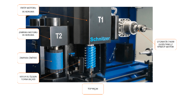
TOP BLADE AND MOTOR
One of the methods of safely taking rough chips from the workpiece. Also, this system can be used to create precise flat surfaces. The speeds can be adjusted in the work program or from the control panel. Top blades are installed and removed with two keys, different methods are used in different machines.
This system used in Schnitzer CNC wood lathe machines speeds up production by safely taking the desired amount of rough chips. A simple and safe binding technique is chosen to remove and install the blade.
SPINDLE MOTOR AND MILLING SYSTEMS
The machine element created to apply various motifs to the surface of flat or cylindrical parts with carving and relief, fillet, spiral, surface cleaning operations, as well as the ability to apply structural attachments such as holes and grooves, is found in Schnitzer CNC wood lathe machines.
The milling motor (spindle) with automatic tool changing feature moves on precise mils and slides.
SHARP BLADE, TURNING BLADES, AND KNIFE SYSTEM
Cutting systems that separate chips from rotating wood in different methods in turning system. The knife, referred to as kater, is a hard metal tip that is attached to a metallic body in different shapes. The knife is connected to the machine with a structural system that moves with pneumatic pistons.
MAGAZINE
The mechanism on which collets (tool holder) and pen blades are mounted, which are either flat or circular. Flat (sequential) magazines are usually fixed, while circular magazines are rotated by a step motor drive. Tool changing motors and magazines must be used for operations in which multiple cutters are used.
CONTROL UNIT
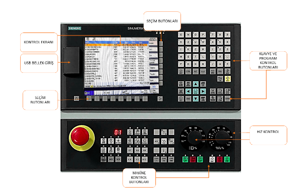
CNC wood machines are computer systems that control all operations. In complex operations, it is necessary for the control computer to have control buttons that will also control the general system.
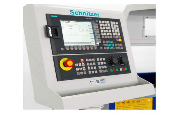
Schnitzer wood lathe machines use SIEMENS brand control unit.
MOTION MOTORS
In 4-axis CNC wood lathe machines, in addition to the basic X, Y, Z axes, there is an A, rotating axis. All of these movements are done with the help of servo and step motors. For more information see Cnc router.
OPERATING SYSTEM
Machine operating systems may vary depending on the characteristics of the job. Although the control panel and operating systems may be different, the job program must be compatible with the machine.
Schnitzer CNC wood lathe machines use the SCHNITZER CAM PROGRAM, which offers easy-to-use simulation options and has proven successful.
OPERATING THE MACHINE
Before starting the machine, make sure there is sufficient air pressure on the machine.
Make sure there is no abnormal condition that could prevent the machine from working. (sharpness of cutting tools, materials that may interfere with work on the machine, the condition of the lubrication system, etc.)
Turning on the main power switch, opening the program:
LOADING AND RUNNING THE PROGRAM TO THE MACHINE
Different methods can be used to load the work program into CNC machines. After the work program is loaded into the MACHINE, IT IS STARTED ACCORDING TO THE FOLLOWING ORDER OF OPERATIONS.
LOADING THE PROGRAM
After the program is loaded, the speed and rotation gears are brought to the lowest level, the emergency stop is opened.
CONNECTING THE PART TO THE MACHINE
A few steps must be taken to connect the part to the machine, as listed below.
- The jaws are adjusted by drawing the heads on the corners and marking them.
- The marked places are held between the mandrel and the traveling mandrel, and the clamping feet are brought to the corners and fixed with bolts.
SCHNITZERCAM PROGRAM
Many cam programs have a LATHE (turning) unit. In addition to general purpose programs, programs specifically prepared for machines can also be seen. Programs are mostly CAD-CAM features. Additionally, 2 or 3 dimensional drawings drawn in alternative CAD programs can also be processed. The image shows the SCHNITZERCAM program interface.
SCREEN TABS:
Command tabs that provide transition between screens. The menu located in the upper left corner of the screen is used to perform operations or view the operation.
DRAWING AND EDITING MENU COMMANDS
2-dimensional drawing and editing commands are included in the basic CAD menu.
The commands and meanings are briefly given in the menu below, and detailed explanations will not be given in order to avoid increasing the volume of the book.
Using previously learned CAD programs is very important in terms of time.
OPERATION MENU COMMANDS
This is the command group where all turning and decoration operations are made. The command menu that contains all turning operations from basic parameter settings to creating G-code is the command menu.
Having multiple operations’ G-codes in the order of operations makes the control of the program easy.
NEW PAGE
Opens a new working page, and some CAM programs reset settings with this page.
SETTINGS
Is used to adjust material measurements and properties, cutter tool settings, and process settings through this menu.
In the opened sub-menu, the necessary material and cutting values are entered and the process is started.
PROFILE FOOT (DOUBLE PROFILE)
Is a command used in a lathe machine to process various workpieces that consist of similar or different profiles.
After entering the command, the necessary parameter input is made through the opened sub-menu and the process is completed.
The most important thing to consider when processing is that the beginning and end of the drawing must be in the direction of an axis.
Precautions must be taken to ensure that the center of the milling cutter does not collide with the center of the cone. Additionally, if double profiling is to be performed, the two surfaces must be drawn.
The following steps are followed to produce a profile foot:
- The foot axis is designed so that it will come to the mill.
- The foot is tested in the drawing for production. The point is monitored to make sure the top blade does not collide with the point mill.
- The workpiece is attached to the machine, processed in the CAM program, and loaded into the machine the process is completed.
For the process of creating a foot program, please refer to the images below.
ROUGH-FINE TURNING
Is a command that turns a square sectioned piece into a cylindrical shape by attaching it and performing rough and fine machining. Only half of the foot needs to be drawn for turning.
The necessary values are entered through the opened sub-menu and preparations are made for turning.
The following procedure should be followed for turning.
EMPTY MATERIAL
Is a command to pick up pre-prepared workpieces for various operations. Necessary selections and measurements are made in the opened sub-menu.
THREAD
Is a command used to make the desired number and size of threads (screws) along the entire or a part of the workpiece, or to make screws on turning or flat surfaces. The necessary values are entered and the process is completed through the opened sub-menu.
The thread is created by making a straight line of the desired length on the surface where the thread will be made, and the depth of the thread is not entered.
The following procedure is followed for making threads in a cylindrical piece.
Note: Wait for the completion of the first process, and codes for the second process are generated after the tool path lines are output.
POCKET EMPTYING
Is a command used to make a pocket or groove on the desired surface of the workpiece being turned to the desired size. The necessary values are entered and the process is completed through the opened sub-menu.
The following procedure is followed for emptying a pocket:
Note: Wait for the completion of the first process, and codes for the second process are generated after the tool path lines are output.
HOLE DRILLING
Is a command used to drill the desired number and size of holes on the desired surface of the turned workpiece. The necessary values are entered and the process is completed through the opened sub-menu.
The following procedure is followed for drilling holes.
OPEN CURVE SURFACE PROCESSING
Is a command used to process linear motifs on turned surfaces. The necessary values are entered and the process is completed through the opened sub-menus.
The following procedure is followed for applying the open curve surface processing command:
V-Blade Surface Processing
Is a command used to engrave the surface of turned workpieces or flat workpieces with the skill of a V-blade. The engraving depth is proportional to the angle of the V-blade and the rounding of the drawing.
The necessary values are entered and the process is completed through the opened sub-menu.
The following procedure is followed for applying the V-processing command.
3D DRAWING ACQUISITION
Is a command used to import work drawn in different CAD programs into the current CAM program. It accepts all STL extension files.
Round-nosed (spherical) cutters must be defined for curved surfaces in scan-based turning operations, and flat-mouthed cutters (End Mill) for flat surfaces. Rough and fine machining amounts are determined according to the size, precision, and measurements of the workpiece and cutters.
The necessary values are entered and the process is completed through the opened sub-menu.
EDGE BREAKING
Is a command used for breaking edges in single or multiple profiling operations. The command is only applied for the “X” axis, and a test is done before the application to ensure that the top blade does not collide with the mills.
The necessary values are entered and the process is completed through the opened sub-menu.
The following procedure is followed for applying the edge breaking command.
G-CODE SAVING
Is a command used to convert all the work done into “G” codes. The “G” code extension selected according to the machine operating system must be selected.
The work is saved as a file, and each program makes a record in the extension specified for itself.
G-Code File
MACHINE CUTTER CHANGING
The methods of changing the cutters used according to the structure of the lathe machines may vary. The process is carried out according to the methods specified by the machine manufacturers for this purpose.
TOP BLADE CHANGING
The “T1” top blade is detached and attached with the help of two keys in various techniques. No settings are made. However, a reset may be necessary again due to a decrease in measurement caused by an unknown cause after the initial reset.
The following procedure is followed for resetting the top blade.
TOP BLADE REMOVAL-ATTACHMENT METHOD
LATHE BLADE CHANGING
Lathe blades of different properties and sizes are generally attached to metal attachments called “KATER” with various bolts. They are removed when they are worn out. Some types of cutters are single-use and are replaced after both sides are used.
LATHE BLADE REMOVAL-ATTACHMENT METHODS
The following procedure is followed for resetting the lathe blade.
MILLING BLADE CHANGING
For the subject of milling blade removal-attachment, see Unit 3 Cnc Router. The same procedures are also performed for Cnc lathe machines. The following procedure is followed for introducing and resetting the cutters in the magazine.
MAINTENANCE OF THE MACHINE:
Cnc machines, like other machines and workbenches, also need daily, weekly and annual maintenance. Periodic maintenance of the machine extends its life, increases job safety, improves the quality of the produced work, and avoids loss of work due to efficiency.
DAILY MAINTENANCE: Cleaning the machine at the end of the day, cleaning the beds and slides from dust, checking and replacing frequently used cutters if necessary.
WEEKLY MAINTENANCE: Along with daily maintenance, the lubrication system is checked according to the amount of work of the machine, the air system, hoses, are checked, and any malfunctions are repaired. The moving parts of the machine are checked, lubricated parts are lubricated.
YEARLY MAINTENANCE: Machine slides and cars, belts and pulleys, air systems, electric connections are checked, and also the nut bolts used for the moving parts are checked, necessary changes are made.
The bearings of the machine are checked, all necessary maintenance activities such as lubrication and replacement are carried out.
MACHINE OPERATION AND SAFETY RULES:
- The machine must not be operated without adequate training on the machine.
- The machine’s processing characteristics must be known and should not be operated beyond its limits.
- Machine processing speeds must be determined according to the characteristics of the workpiece and cutters, as well as the material properties.
- The machine cannot be operated without the covers being closed.
- It is dangerous to operate the machine without adequate air pressure.
- It is possible but dangerous to manually sand the machine.
- Workpieces connected to the machine must not be cracked, rotten(in advanced level), or have rough edges, also bowed parts are dangerous until they become cylindrical.
- The speed of the cutters should be low at the first contact with the workpiece and must be manually controlled if necessary.
- The speed of the lathe should be reduced when processing long workpieces, otherwise the piece may fly off.
- Workpieces for mass production should be cut to standard lengths, very short or very long pieces cannot be well held or may crack by the machine.
- When processing thin parts with fine edges, necessary trials should be done on the drawing to prevent the cutter from hitting the edges and in practice, the situation should be observed by reducing the speeds.
- Adjustments must be made to prevent jamming of parts in charger machines.
- It must be checked that the magazine is properly and correctly placed on the tool holders.
- When preparing the work program, the order of the cutters in the magazine should be considered.
- It is important to work with sharp and appropriate cutters, and not to overdo rough handling, as it can damage the machine or workpiece.
- Workpieces with a lathe attachment should not be used unless they are very well secured.
- Check that the tailstock clamp is securely tightened.
- Check that the machine’s lubrication system is working properly and fix any malfunctions.
- Take the necessary measures to ensure that the chips are easily removed.
- The tailstock clamp should not have too much or too little clamping pressure.
- If the workpiece breaks or comes loose, do not intervene without stopping the machine.